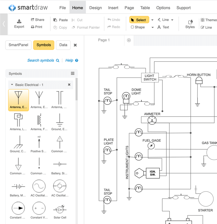

Three Phase Electrical Wiring Installation Diagram they are mostly used for wiring installation in home and industries. It really helps in showing the interconnections in different equipment such as electrical panel and distribution boxes etc. Wiring diagram shows a pictorial view of the components such that it resembles its electrical connection, arrangement and position in real circuit.

Vertical and horizontal lines are used to represent wires and each line represents a single wire that connects between electrical components. The wiring diagram is used for the representation of electrical components in their approximate physical location using their specific symbols and their interconnections using lines. It passes through multiple stations, whose function and ratings are also mentioned but their electrical connections are not highlighted. This diagram clearly shows a 3 phase power generating station that transmits the power to the consumers below. The SLD diagram uses dedicated electrical symbols and icon for different components.Ī common example of a 3 phase power circuit to represent using a single line diagram would be the power transmission and distribution to the consumers. They are used for determining and isolating any faulty equipment in any power system during troubleshooting. it simplify complex 3 phase power circuits by showing all the electrical components and their interconnection. Single line diagram does not show the electrical connections of the component but it may show the size and ratings of the components being used. As the name suggests, a single line is used to denote the multiple power lines such as in 3 phase system. Single Line diagram ( SLD) or one-line diagram is the representation of an electrical circuit using a single line.

One can easily troubleshoot certain schematic by applying electronic circuit theory.
#Electrical diagram program free series#
It helps in showing the series and parallel connection between the components and the exact terminal connection between them.

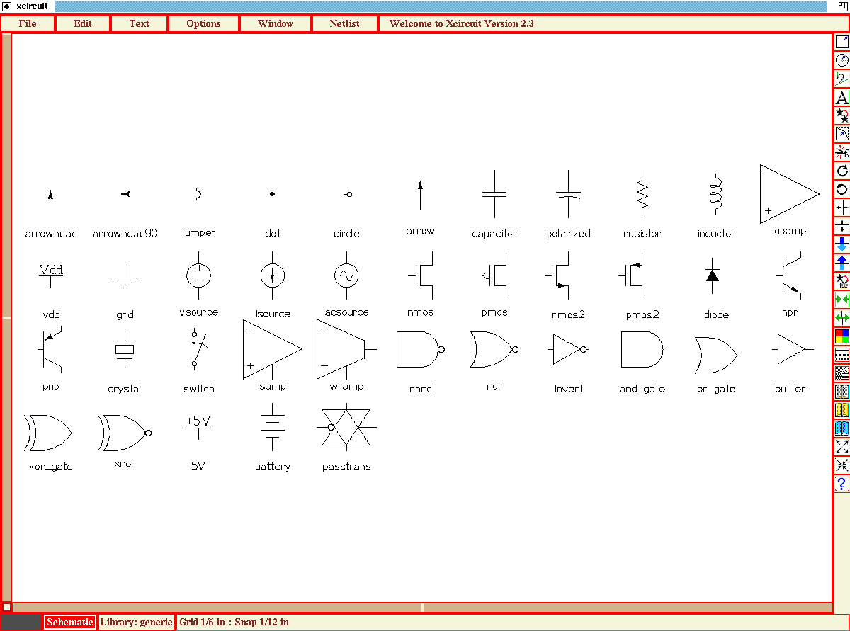
Unlike wiring diagram, it does not specify the real location of the components, the line between the components does not represent real distance between them. The schematic diagram of an electrical circuit shows the complete electrical connections between components using their symbols and lines.


 0 kommentar(er)
